Standard Keensert Drill Chart 3 Installation and Removal Drill out old threads with a standard drill Note Drill is oversize see charts for proper dimensions Chamfer the hole with a standard countersink 82 100 Tap new threads with a standard tap See charts for proper size and depth Screw in the insert until slightly below surface
Insert Installation Drill with a standard drill as listed for each part number Countersink with a Tap with a standard standard countersink 82 to 100 Unified Thread Series tap Screw in insert with fingers or installation tool Insert is designed to stop at the correct depth below the surface of the casting Time saved using self broaching KEENSERTS Inserts and Studs has been estimated at upwards of 7 minutes per individual installation Self Broaching KEENSERTS Inserts and Studs Six simple steps 1 Drill with a standard drill 2 Countersink with a standard countersink 82 to 100 3 Tap with a standard unified thread series tap 4
Standard Keensert Drill Chart
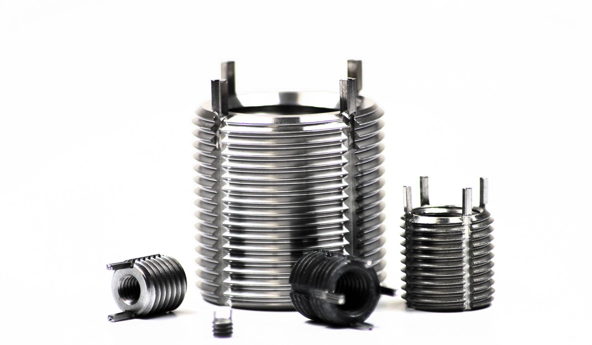
Standard Keensert Drill Chart
https://www.clarendonsf.com/usercontent/img/col-24/4370.jpg
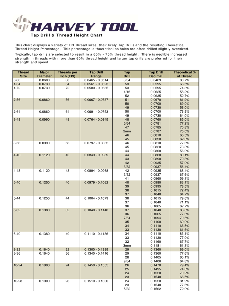
Tap Drill And Thread Height Chart Edit Fill Sign Online Handypdf
https://handypdf.com/resources/formfile/images/fb/source_images/tap-drill-and-thread-height-chart-d1.png

Metric Drill Bit Size Chart Pdf Cody Huynh
https://i.pinimg.com/736x/f9/1f/2f/f91f2fe1b271db4f1454a11f725d616e.jpg
Order on Line Keysert Key Locking Screw Thread Inserts Carbon Steel Inserts Stainless Steel Inserts Keylocking Inserts Keylocking inserts are used to repair stripped damaged or worn out threads Installed with standard drills and taps No pre winder required No tang break off A Keensert is a solid threaded bushing style insert that is available in standard dimension metric and inch sizes The insert is provided with keys that lock the insert to the workpiece during installation As supplied the locking keys are initially located in the extended position as shown here
Features of KEENSERTS Drill with standard drill Countersink with cone countersink 80 100 Thread with standard tap Screw in by hand or with installation tool see installation data pages B 1 to B 4 Lock in Place drive the kees into place by hand or in a press with the appropriate D modified tap drill inch E countersink inch 0 01 mm Thread F Thread F Hand installation tool part no Drill Drill
More picture related to Standard Keensert Drill Chart
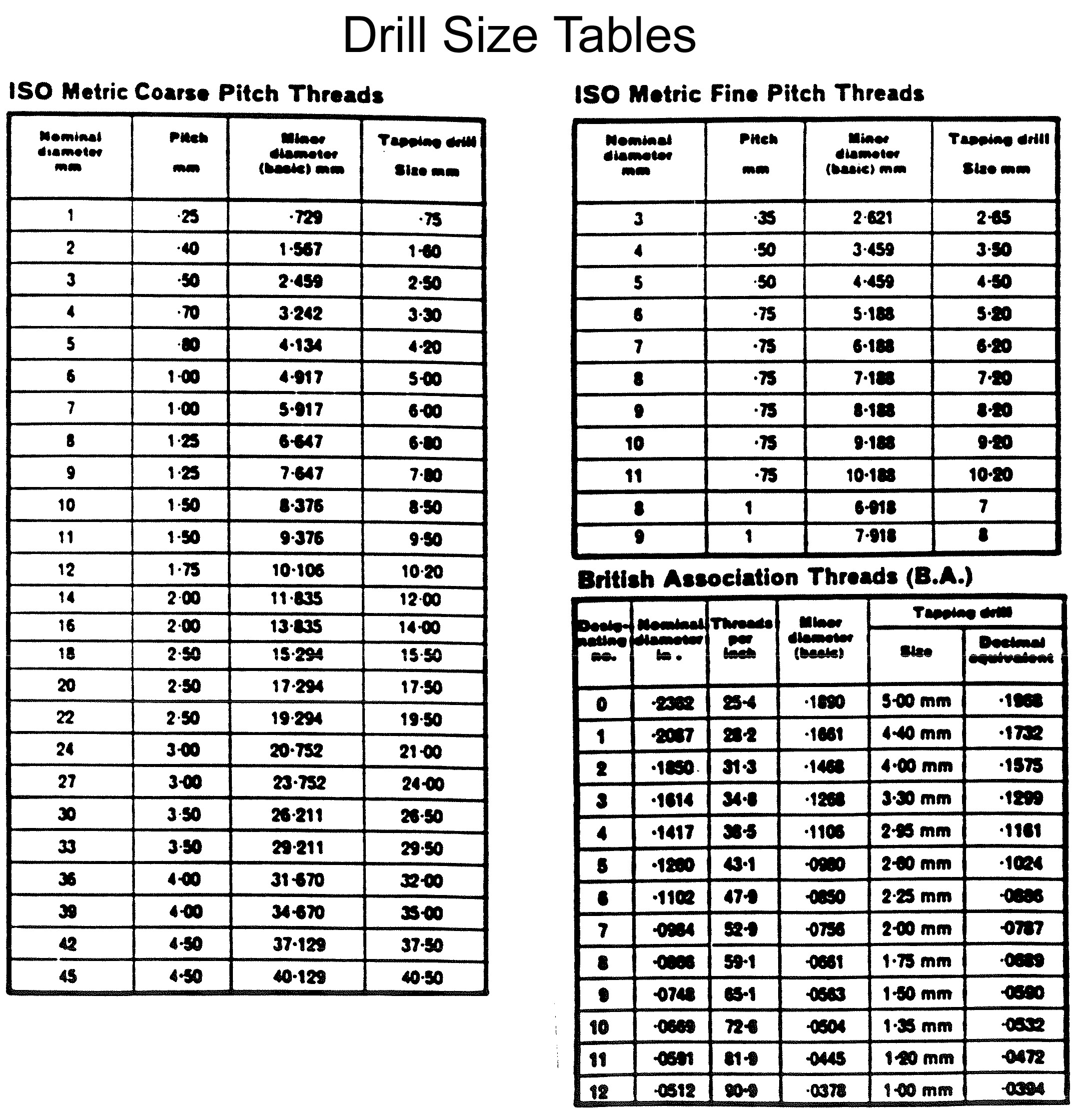
Keensert Tap Drill Chart
http://www-mdp.eng.cam.ac.uk/nagty/resources/enginfo/cookbook/manufacturing/tapping/drill_table.jpg

Helicoil Tap Drill Size Chart
https://i.pinimg.com/originals/08/05/5f/08055ffeb0d5977d6722eddee6900a05.jpg

Keensert Solid Inserts
http://www.hfsindustrial.com/pub/media/resources/images/image/thumbnails/3-2021-4-e-inserts_knhm.pdf.jpg?1
Removal of KEENSERTS Inserts It is unlikely that KEENSERTS inserts will ever have to be removed since their threads are stronger than original threads If removal is necessary however follow these simple steps 1 Use STANDARD DRILL to remove insert material between Kees 2 Deflect Kees inward and break off 3 Remove insert with Camloc Keenserts provide high strength joints in low strength materials Typical applications are transmission housings electronic equipment and suspension units Available in inch and metric thread sizes the stainless steel solid bushing configuration of the Keenserts guarantees the quality of the internal thread before installation
10 32 to 1 1 2 12 UNF Fine Key Inserts are installed using standard drills and taps but the required tap drill size is slightly larger than normal for that OD thread size See Installation Data table below for the appropriate tap drill size View in Catalog Page Contact Customer Service Application Information Installation Removal Material Stud Removal Cut off the nut end at a point just above the surface Use standard drill and depth as listed for applicable stud and drill to remove material between KEES Deflect KEES inward and break off Remove studs with E Z Out type tool An identical stud can now be installed in the original hole No re work of the hole will be necessary
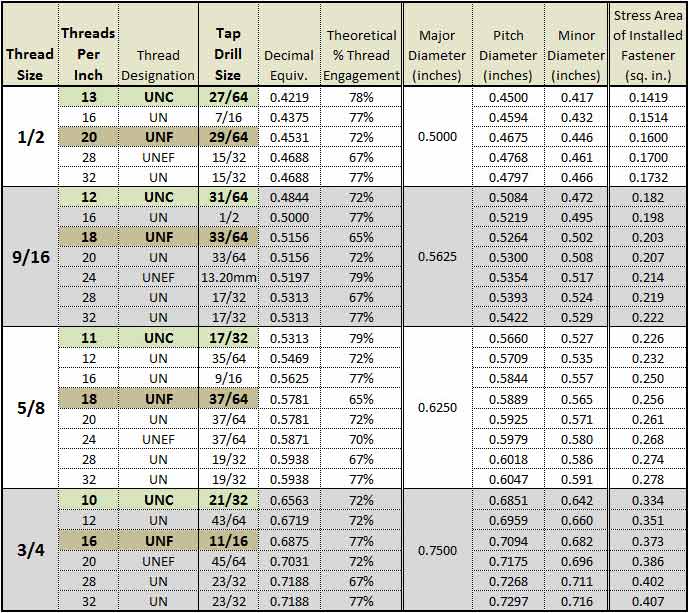
Keensert Thread Chart A Visual Reference Of Charts Chart Master
http://www.repairengineering.com/image-files/xtap-drill-chart-.5-.75.jpg.pagespeed.ic.GXBG6FRbx_.jpg
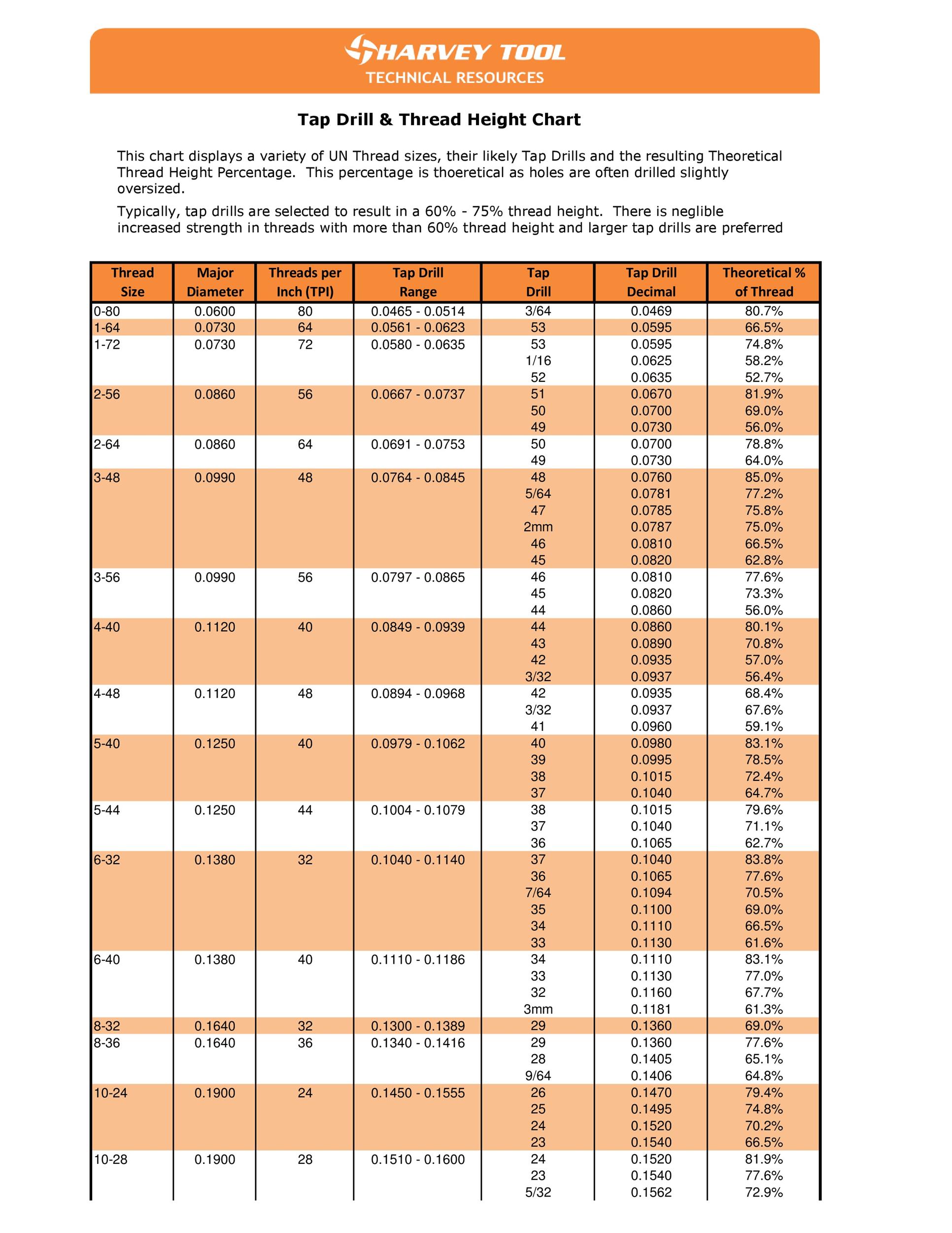
Hilaire Printable Drill Size Chart Tristan Website
http://templatelab.com/wp-content/uploads/2016/09/tap-drill-chart-17.jpg
Standard Keensert Drill Chart - Features of KEENSERTS Drill with standard drill Countersink with cone countersink 80 100 Thread with standard tap Screw in by hand or with installation tool see installation data pages B 1 to B 4 Lock in Place drive the kees into place by hand or in a press with the appropriate