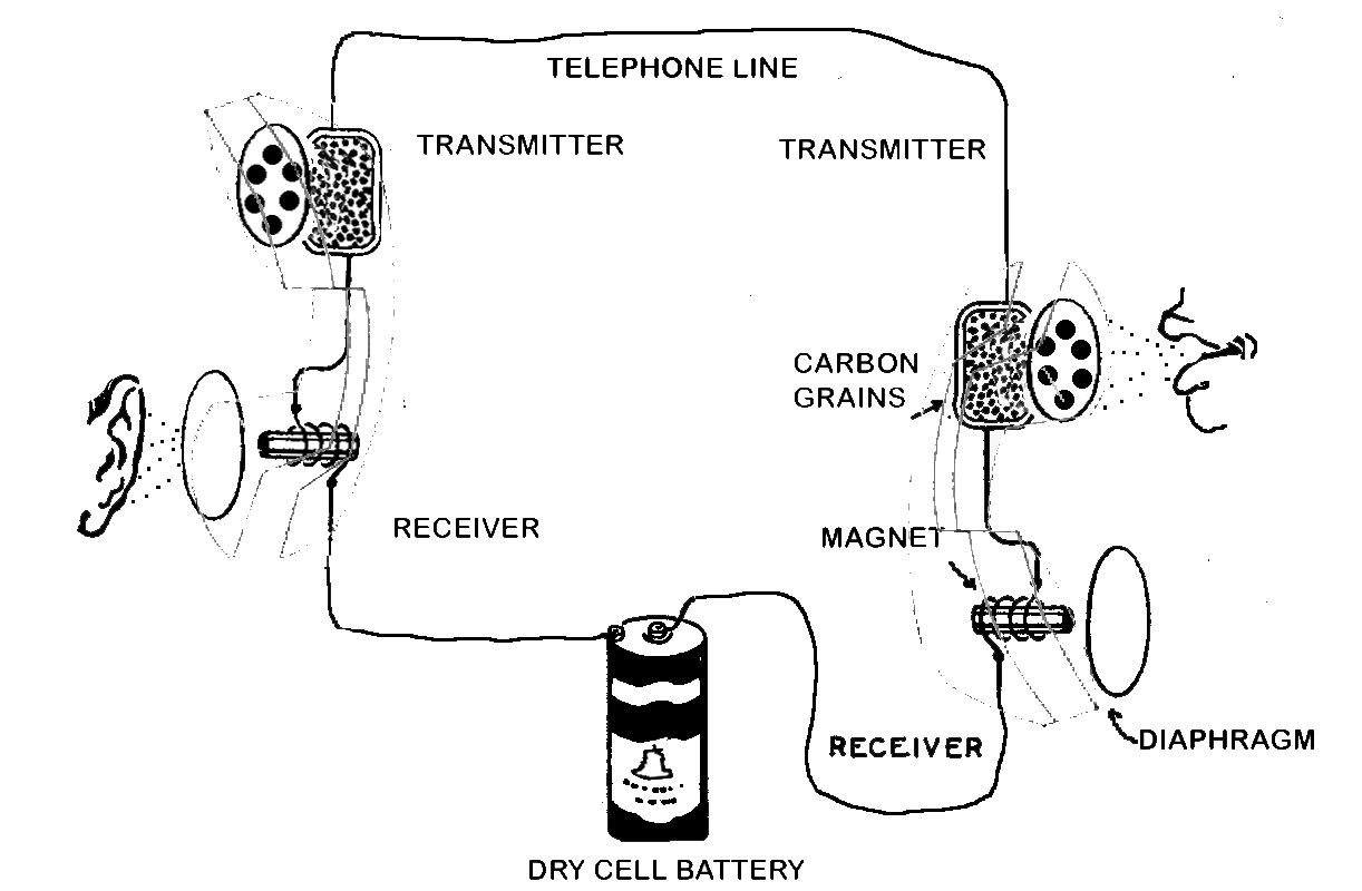
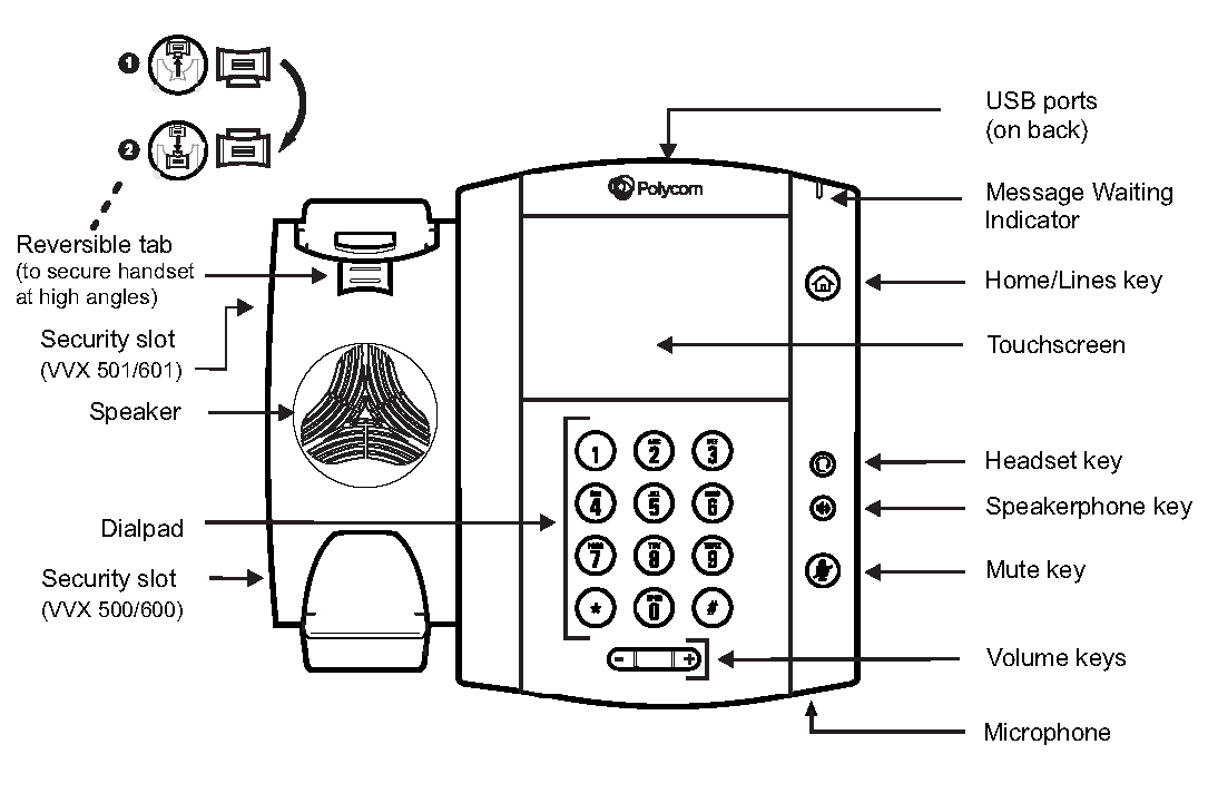
Simple Telephone Diagram A switch to connect and disconnect the phone from the network This switch is generally called the hook switch It connects when you lift the handset A speaker This is generally a little 50 cent 8 ohm speaker of some sort A microphone In the past telephone microphones have been as simple as carbon granules compressed between two thin metal plates
A simplified circuit and Block diagram of the telephone set is shown in the figure Block Diagram of Telephone Set Circuit Diagram Of Telephone Set Circuit diagram of subscriber s telephone set Telephone Set Transmitter Carbon Granule Transmitter Microphone in telephony is regarded as transmitter In this video we learn how to make telephone easy at home its very interesting project in this project we use simple npn transistor mic and speaker connect with long wire its basic of
Simple Telephone Diagram

Simple Telephone Diagram
http://www.antiquetelephonehistory.com/images/teleworks.gif

How To Make Telephone Easy At Home Step By Step With Circuit Diagram
https://i.ytimg.com/vi/VKnEeH5h0Kc/maxresdefault.jpg

How To Draw A Telephone Step By Step Telephone Drawing Easy YouTube
https://i.ytimg.com/vi/X2vt3qWdscw/maxresdefault.jpg
Advantages it is a simple method which can be implemented in simple terminals electromagnetic phones with dialing disk Dual Tone Multi Frequency DTMF dialing The basic telephone system enables voice communication between two or more parties by converting sound waves into electrical signals during transmission at the transmitter end At the receiver electrical signals are converted back into sound waves
Shown in the image above is the hook switch which connects or disconnects the telephone from line in It is a simple switch having a contact and spring assembly The spring holds to two metal contact platforms out of which one is stationary and the other is movable In the pressed state the movable platform is pressed downwards where it doesn Simple English Sloven ina A telephone is a telecommunications device that permits two or more users to conduct a conversation when they are too far apart to be easily heard directly The circuit diagram of the model 202 shows the direct connection of the transmitter to the line while the receiver was inductively coupled
More picture related to Simple Telephone Diagram

Draw Telephone Easy Steps How To Draw Telephone Easy Step By Step For
https://i.ytimg.com/vi/YVeKOe1Bleo/maxresdefault.jpg

DIAGRAM Parts Of A Phone Diagram MYDIAGRAM ONLINE
https://rest.kb.iu.edu/image/a102l.png

Basic Telephone Wiring Diagram
https://2.bp.blogspot.com/-2p8Y60OBqLQ/TmnK-9xcjxI/AAAAAAAAABc/6UuaFR5KHd4/s1600/RJ-14+Pix+1.jpg
Telephone Receiver Circuit The ringer section comprises R1 C1 and a buzzer If your telephone has a loud ringer this circuit can be avoided A bridge rectifier consisting of diodes D1 through D4 protects the circuit from any polarity change in the telephone line PNP transistor MPS A92 T1 is the main interface transistor Circuit Diagram Telephone Circuits Contact About Links Telephone Amplifier Circuit An easy to build circuit of telephone conversation amplifier The circuit uses a common LM386 IC the circuit require no power supply it will run by using the power from phone line Simple circuit of a telephone ring tone gererator the circuit uses CD
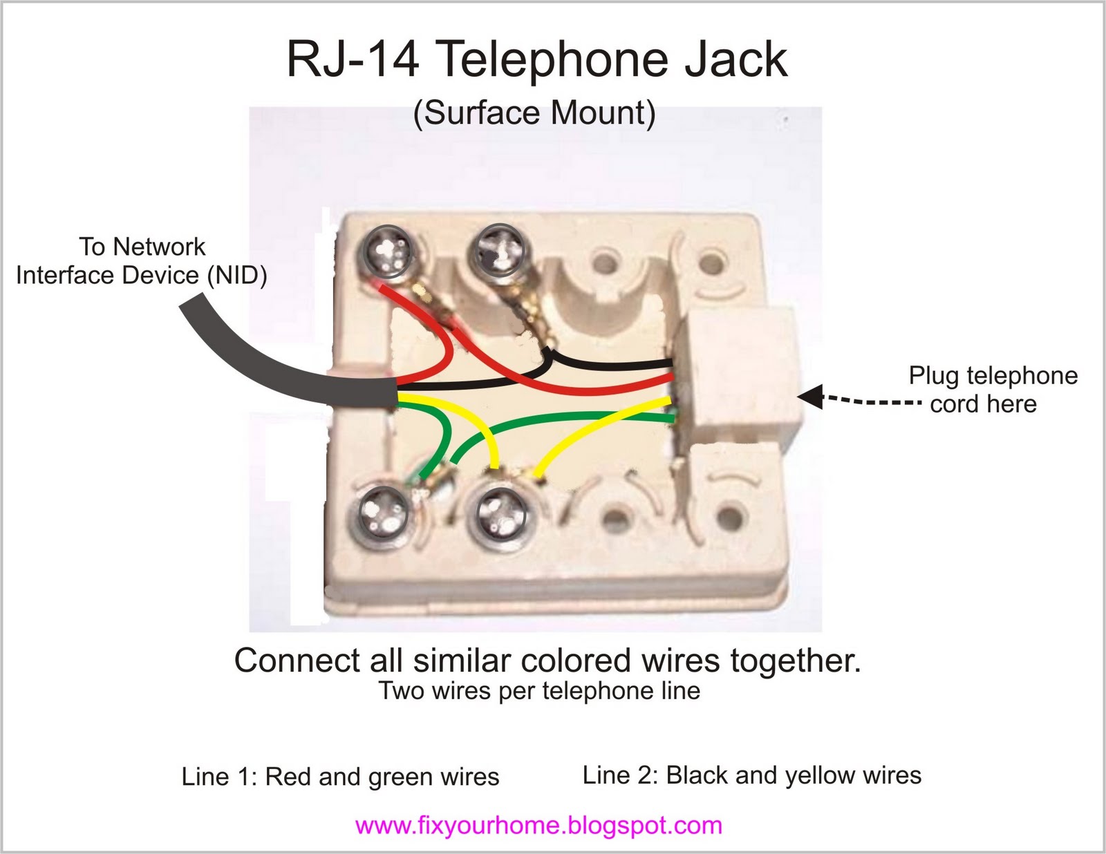
Click here for the Wiring Diagrams Technical Library list view by Manufacturer and Model Hint Also check BSPs GSPs and technical bulletins for wiring options and detailed technical information Search for the phone model and wiring or schematic e g North 5H6 wiring This is a library of basic schematics wiring diagrams and other information that can be useful to anyone 6 Attach the telephone jack to your Network Interface Device box You ll use the colored screw sections in the Network Interface Box to do this Clip the end of the phone cable off Strip an inch off of the end of each of the colored wires Separate the green wire and the red wire

Alexander Graham Bell
https://svitppt.com.ua/images/16/15197/960/img6.jpg

Basic Telephone Wiring Diagram
https://i.ytimg.com/vi/0MXh7dvPC_E/maxresdefault.jpg
Simple Telephone Diagram - Advantages it is a simple method which can be implemented in simple terminals electromagnetic phones with dialing disk Dual Tone Multi Frequency DTMF dialing