Keensert Drill Chart 3 Installation and Removal Drill out old threads with a standard drill Note Drill is oversize see charts for proper dimensions Chamfer the hole with a standard countersink 82 100 Tap new threads with a standard tap See charts for proper size and depth Screw in the insert until slightly below surface
KEENSERTS Inserts Installation Removal Broach Cont d Insert Removal It is unlikely that KEENSERTS inserts will ever have to be removed since their threads arestronger than original threads If removal is necessary however follow these simple steps Use standard drill as listed for each part number to remove insert material between KEES A Keensert is a solid threaded bushing style insert that is available in standard dimension metric and inch sizes The insert is provided with keys that lock the insert to the workpiece during installation As supplied the locking keys are initially located in the extended position as shown here
Keensert Drill Chart
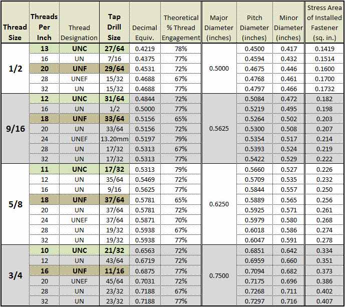
Keensert Drill Chart
http://www.repairengineering.com/image-files/xtap-drill-chart-.5-.75.jpg.pagespeed.ic.GXBG6FRbx_.jpg

Keensert Drill And Tap Chart Labb By AG
http://www.thread-insert.com/Content/upload/201976705/201906121555396521762.png
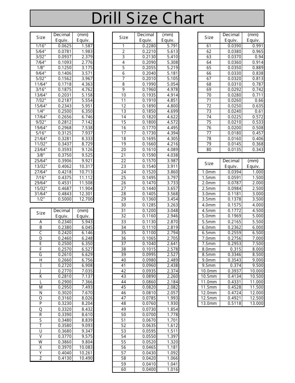
Keensert Tap Drill Chart Formsrilo
https://data.templateroller.com/pdf_docs_html/154/1542/154268/drill-size-chart_print_big.png
Keenserts provide a strong permanent thread in a weaker parent material These easy to install and remove tools are commonly used to repair threads on ferrous non ferrous or non metallic metals like aluminum and magnesium Key inserts are not recommended for use in brittle materials like cast iron and plastic Locate and drill with standard drill to Tap Drill Diameter A 2 Countersink with standard countersink 82 to 100 to Countersink Diameter B KEENSERTS against the threaded hole in the part and allow it to screw in Take Care to align the tool with the axis of the hole When the insert is at the correct depth
Floating Keenserts Floating Keenserts are designed to compensate for radial misalignment from 0 015 for 2 56 up to 0 040 for 10 and larger sizes The Keensert is supplied as a one piece unit Ideal for use where mating panel holes may be off center Features of KEENSERTS Drill with standard drill Countersink with cone countersink 80 100 Thread with standard tap Screw in by hand or with installation tool see installation data pages B 1 to B 4 Lock in Place drive the kees into place by hand or in a press with the appropriate
More picture related to Keensert Drill Chart
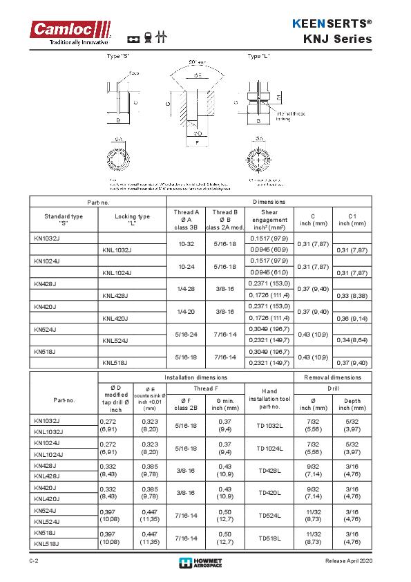
Keensert Solid Inserts
https://www.hfsindustrial.com/pub/media/resources/images/image/thumbnails/4-2020_4-e-inserts_seriesknj.pdf.jpg?1
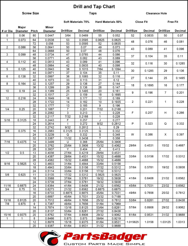
Keensert Tap Drill Chart
https://parts-badger.com/wp-content/uploads/2016/08/Drill-and-Tap-Chart-784x1024.jpg
Keensert Guide Screw Metalworking
https://imgv2-2-f.scribdassets.com/img/document/62421863/original/599a300d09/1566908519?v=1
D modified tap drill inch E countersink inch 0 01 mm Thread F Thread F Hand installation tool part no Drill Drill Key Inserts are also well suited for quick repair of stripped damaged or worn threads A solid version is also available to use as a handy plug to relocate holes drilled or tapped on the wrong location Install with standard drills and taps Important Use tap drill specified in table slightly larger than standard for that thread size
Keylocking inserts are used to repair stripped damaged or worn out threads Installed with standard drills and taps No pre winder required No tang break off Locking keys provide a positive mechanical lock preventing rotation due to vibration or torsion Can be used in most materials Aluminum magnesium cast iron cold rolled steel and plastic Product Information General purpose threaded inserts with a thick heavy duty thread wall suitable for most applications Key Inserts are ideal for thread reinforcement especially when the mating stud or bolt will be removed frequently
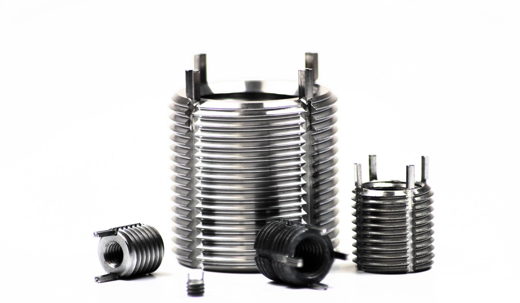
Keensert Drill And Tap Chart Lamer
https://www.clarendonsf.com/usercontent/img/col-24/4370.jpg
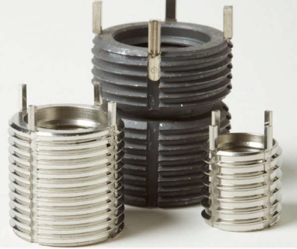
Keensert Drill And Tap Chart Kemele
https://www.aircraftfast.com/images/categories/ms-keensert-inserts.jpg
Keensert Drill Chart - Install Keensert style inserts Screw inserts into tapped holes by hand and place the tip of these tools into the insert Strike the tools with a hammer to drive the keys into the material Tools that feature a spring have a knurled grip on that lets you screw inserts into tapped holes reducing hand fatigue if you re installing many of them To fit over inserts evenly tools have an
